

- Understand what a trimmer potentiometer is and how it functions.
- Learn how trimpots work as both variable resistors and voltage dividers.
- Discover practical wiring pinouts and adjustment tips for your electronics projects.
A trimmer potentiometer, often called a trimpot, is a compact, three-terminal adjustable resistor. If you’ve ever tinkered with electronics breadboards or small circuit boards, chances are you've encountered one. These little devices let you fine-tune resistance or voltage output in your circuit without swapping out fixed resistors—a handy tool when you want precision control in your designs.
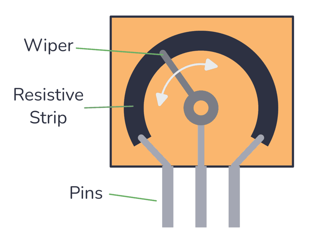
I always start with the basics when working with a trimpot because understanding its core function simplifies more advanced applications. At its heart, a trimmer potentiometer has three pins:
- Two fixed terminals connected at either end of a resistive element.
- One wiper terminal that slides across the resistive material, adjusting the resistance or voltage you tap from it.
When you adjust the wiper by turning the small screw or knob on the trimpot, you change the resistance ratio between the wiper and each fixed terminal. This change allows you to either vary resistance or create a voltage divider that outputs a fractional voltage based on the position of that wiper.
How Does a Trimmer Potentiometer Work?
Think of the trimpot as a tiny adjustable voltage or resistance controller. It operates in two main modes:
- Variable resistor (rheostat) mode: Using only two terminals (one fixed end and the wiper), the trimpot adjusts the resistance between them. This controls current flow, useful in dimmer switches or sensor calibration circuits.
- Voltage divider mode: Connecting all three terminals, you feed voltage across the two fixed ends and take a controlled output voltage from the wiper. This output can range anywhere between zero volts and the input voltage. It’s perfect for setting reference voltages or tuning signal levels.
You don’t need to worry about polarity; you can swap fixed terminals without changing the basic behavior, although this may reverse the direction of increasing resistance or voltage.
Pin Configuration in Detail

- Fixed Terminal 1 (CW): One end of the resistive track.
- Wiper (Terminal 2): The output voltage terminal that slides along the resistive track.
- Fixed Terminal 3 (CCW): The other end of the resistive track.
For typical voltage divider applications, you connect the supply voltage to one fixed terminal and ground to the other. The wiper provides a controllable voltage output somewhere in between.
Practical Uses of Trimpots
- Calibrating sensors: Trimpots allow fine sensitivity adjustment without soldering.
- Setting voltage thresholds: Ideal for adjusting reference values in analog circuits.
- Tuning audio or LED brightness: By varying resistance or voltage, you get smooth control.
- Circuit trimming: Designers use trimpots during prototyping to find optimal resistance values before finalizing design with fixed resistors.
Wiring a Trimpot on a Breadboard
To wire a trimmer potentiometer, plug the three terminals into separate breadboard rows. Connect:
- One fixed terminal to your positive voltage rail (e.g., +5V).
- The other fixed terminal to ground.
- The wiper terminal goes to your measurement point or signal input.
Then, turning the adjustment screw slides the wiper along the resistive element, changing the output voltage measured at the wiper.
For example, if your supply voltage is 5V, turning the wiper adjusts the output voltage anywhere between 0V and 5V. This simple setup is the basis for variable voltage control in countless circuits.
Tips When Using Trimmer Potentiometers

- Limit the current. Most trimpots are designed for low power and maximum current ratings often hover around tens of milliamps. Don’t push them beyond their specifications to avoid damage.
- Measure resistance with power off. Always measure trimpot resistance or continuity without power applied to avoid harming your multimeter or the trimpot.
- Use precision tools for final calibration. Cheap screwdrivers or an improper tool can slip and damage the adjustment screw or the middle wiper.
- Beware of wiper noise. In some circuits, especially audio, you might notice small fluctuations when adjusting or as the wiper moves. Quality trimpots reduce this effect.
Advantages of a Trimmer Potentiometer
- Budget-friendly, compact components perfect for tight spaces.
- Adjustable on-the-fly without needing to desolder.
- Available in different resistance values from a few ohms to megaohms.
- Easy to interface with breadboards or PCB via small pins.
- Suitable for both prototype and final trim adjustment in product design.
A Simple Example: Using a Trimpot as a Voltage Divider
Say you have a 10kΩ trimpot connected across 5V and ground. The voltage at the wiper, V_out, depends on the relative position of the wiper, which splits the resistor into two parts—let’s call them R1 (wiper to one fixed end) and R2 (wiper to the other fixed end).
The output voltage is:
$ V_out = V_in × (R2 / (R1 + R2))$
As you twist the adjustment, the ratio changes smoothly, letting you “dial in” the exact voltage you want.
Trimmer potentiometers might seem small and simple, but their role in electronic circuits is far from trivial. Whether you’re adjusting brightness, tuning sensors, or calibrating signal levels, the trimpot is an essential and versatile tool.
For more technical reference, check out PCB manufacturer WellPCB’s detailed guide on trimpot pinouts and usage: [WellPCB Trimpot Pinout Guide](https://www.wellpcb.com/blog/components/trimpot-pinout/).
FAQ
Q: What is the difference between a trimpot and a regular potentiometer?
A: Trimpots are small potentiometers intended for infrequent adjustments, usually set with screwdrivers and mounted on PCBs, whereas regular potentiometers often have knobs designed for frequent user control.
Q: Can I use a trimpot to control high currents?
A: No. Trimpots are generally rated for low currents (often below 100mA). For higher current loads, use power-rated potentiometers or separate power control components.
Q: How do I know the resistance value of a trimpot?
A: Usually, the resistance is printed on the body using a code (e.g., 103 means 10,000 ohms). You can also measure with a multimeter between the two fixed terminals.
Q: Can I use a trimpot as a rheostat with only two pins?
A: Yes. Connecting the wiper and one fixed terminal lets you use the trimpot as a variable resistor.
Q: How should I connect a trimpot to act as a voltage divider?
A: Connect the power supply voltage to one fixed terminal, ground the other fixed terminal, and take your variable voltage output from the wiper terminal.

%20(1)%20wepb.webp)
